I've got interested in projectors and modding them to use alternate light sources. I had a broken Sanyo (that I broke even more) so I've taken it apart to see how the light tunnel and LCDs are constructed. Here we go...
Here we have the unit with all the circuit boards and power supplies removed. The LCDs have the orange ribbons attached. The light tunnel runs along the back of the unit. The bulb sits in the bottom left.

Here's a close up of the LCD assembly with the ribbons. The ribbon on the right has been removed correctly. The two others have the connector still attached when they were ripped off the motherboard. Oops.

Onto the light tunnel. Here is the first thing the light from the bulb passes through. A fresnel lens I believe.

After that another fresnel..
 .Dunno what this does..
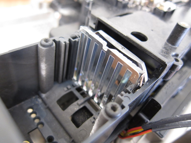
Here it is separated..

Finally in the tunnel.. a standard lens..

After the tunnel the light is split three ways..

Here's another shot of the three way split ( I cut the ribbons from the LCDs to make it easier to see). The pieces of glass are actually dichroic filters (http://en.wikipedia.org/wiki/Dichroic_filter) that reflect one light colour and let the others through.

Here's a shot of the LCDs taken after removing them and the lens from the unit..

The LCD for the Red channel..

It's possible to see an image through the lens.


With the LCD removed you can see the image on the surface of the prism.

There's more lenses and filters (possibly UV) shown here that are part of the unit..

The LCDs appear to require a lot of cooling. Here's a picture of the three fans and air ducts that are under the LCDs

Next up on this.. I'm going to try and get some white smoke drifting around the tunnel so I can see how the light from a torch is split.
No comments:
Post a Comment